DIY adjustable lab power supply Circuit Diagram
DIY adjustable lab power supply Circuit Diagram Once again in order to make sure the
Explore Everything, Discover More Aiden Grant.
DIY adjustable lab power supply Circuit Diagram Once again in order to make sure the
Microcontrollers Diy projects gadgets Circuit Diagram Voice controlled wheel chair using Arduino. Voice controlled wheel
DIY BRIDGE RECTIFIER BETTER LOOKING Circuit Diagram The full wave rectifier circuit consists of two
Applications of IoT and scenario of intelligent transportation Circuit Diagram On the basis of intelligent
PLC ExplanationProgrammable Logic Controller Basics2 Circuit Diagram Logic Circuit Must-Haves. You can easily configure an
Homeowners Guide to Electrical Grounding and How It Works Circuit Diagram Solid grounding refers to
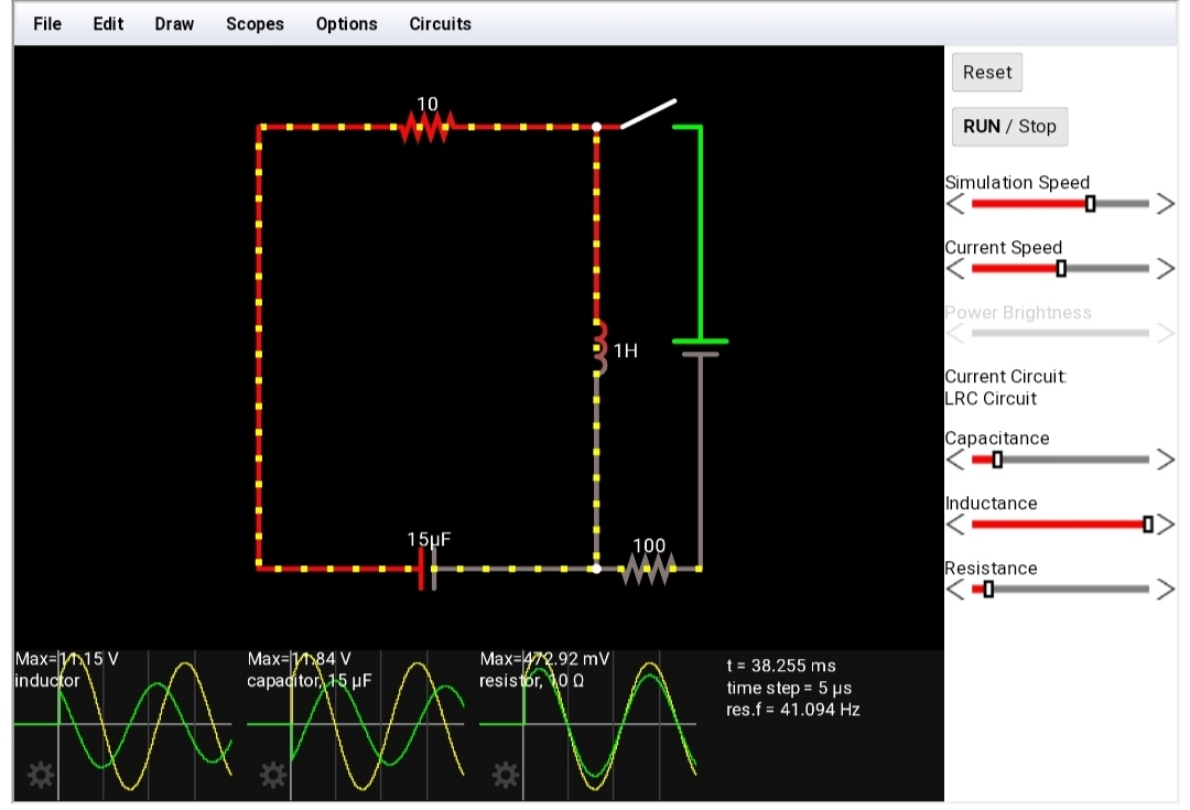
Best Free Circuit Simulator The Best 13 Simulator software Circuit Diagram But there's a problem:
emotion detected by artificial intelligence AI Circuit Diagram The Speech Emotion Recognition app successfully identifies
What is Pattern Recognition A Gentle Introduction 2025 Circuit Diagram How To Run The Examples
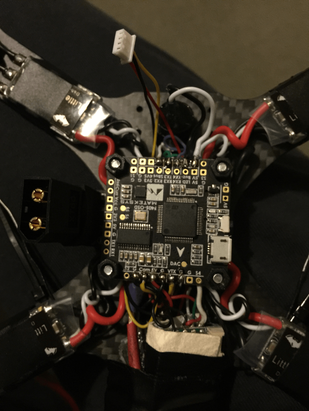
How to Build A Drone DIY Step by Step Guide 2023 Circuit Diagram Just make
Pass Filter Design with Microcontroller Circuit Diagram The formula and schematic for the LC low
DIY Kit Ultrasonic Range Finder Circuit Diagram In this Arduino tutorial I will show you
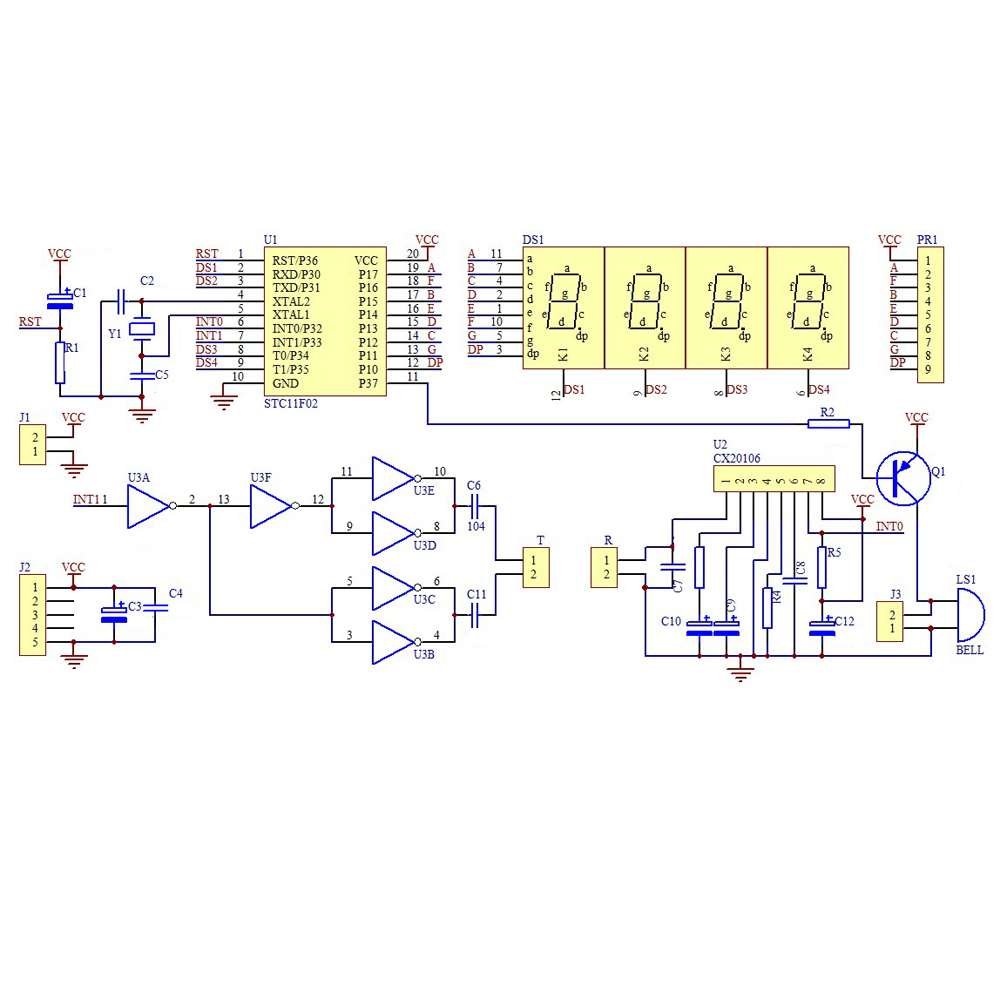
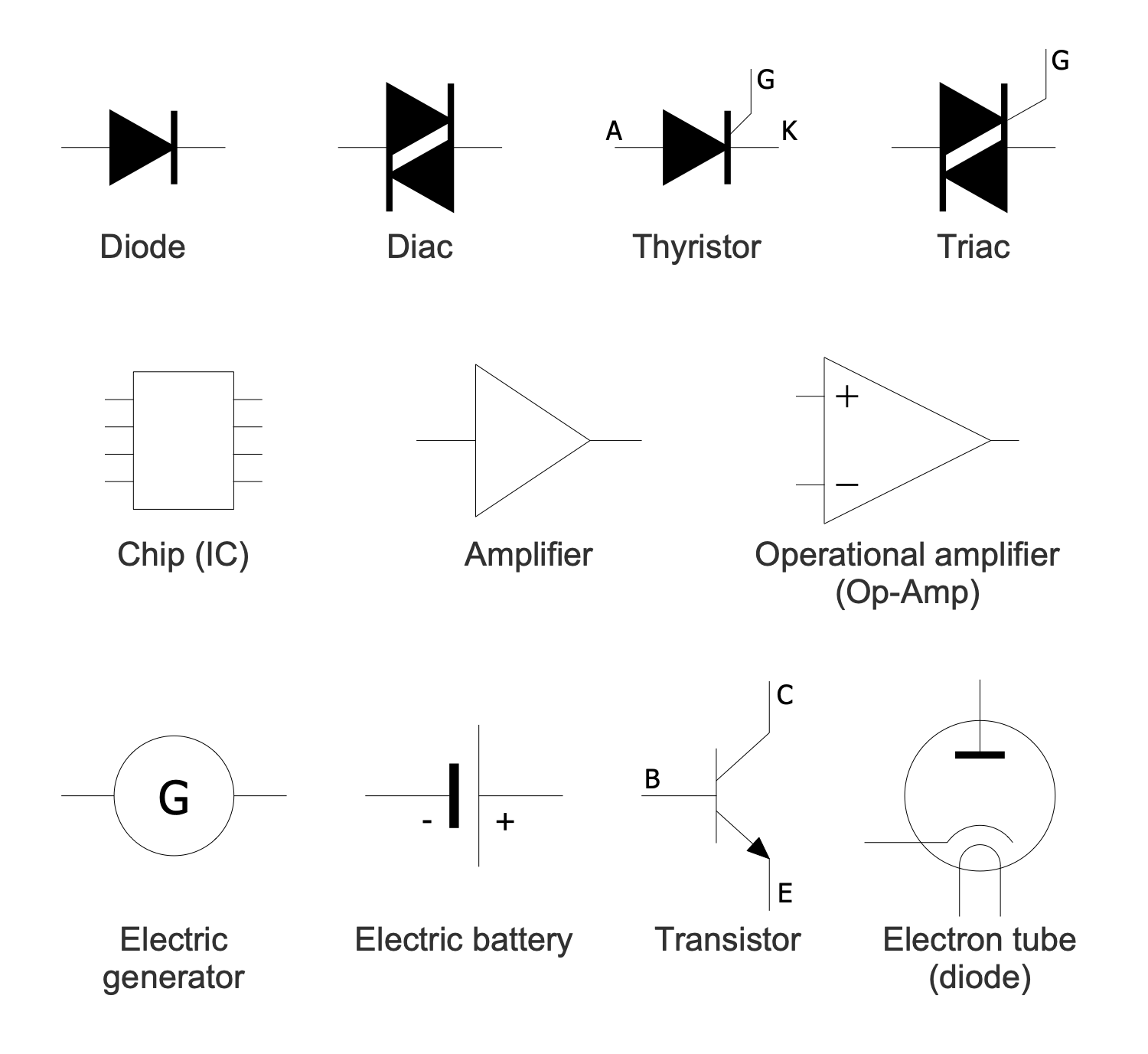
Basic Circuit Diagrams Solution Find the integrated circuit symbol in the schematic symbols overview. An
3 Schematic Circuit using Proteus Design Suite 8 Source Researcher Circuit Diagram Circuit Simulation using
Super Simple High Power LED Driver 3 Steps Circuit Diagram LED Driver Circuit. The schematic
Power amp design for audio electronics class Circuit Diagram 4-transistor audio amplifier circuit This is
Scheme implemented for the design of the measurer of the current Circuit Diagram The Micro
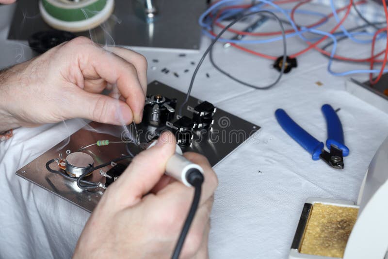
Soldering Electronics with Different Tools Stock Photo Circuit Diagram Having the best soldering iron for
The Light Will Be Automatically ON When You Will Open The DoorSimple Circuit Diagram -You
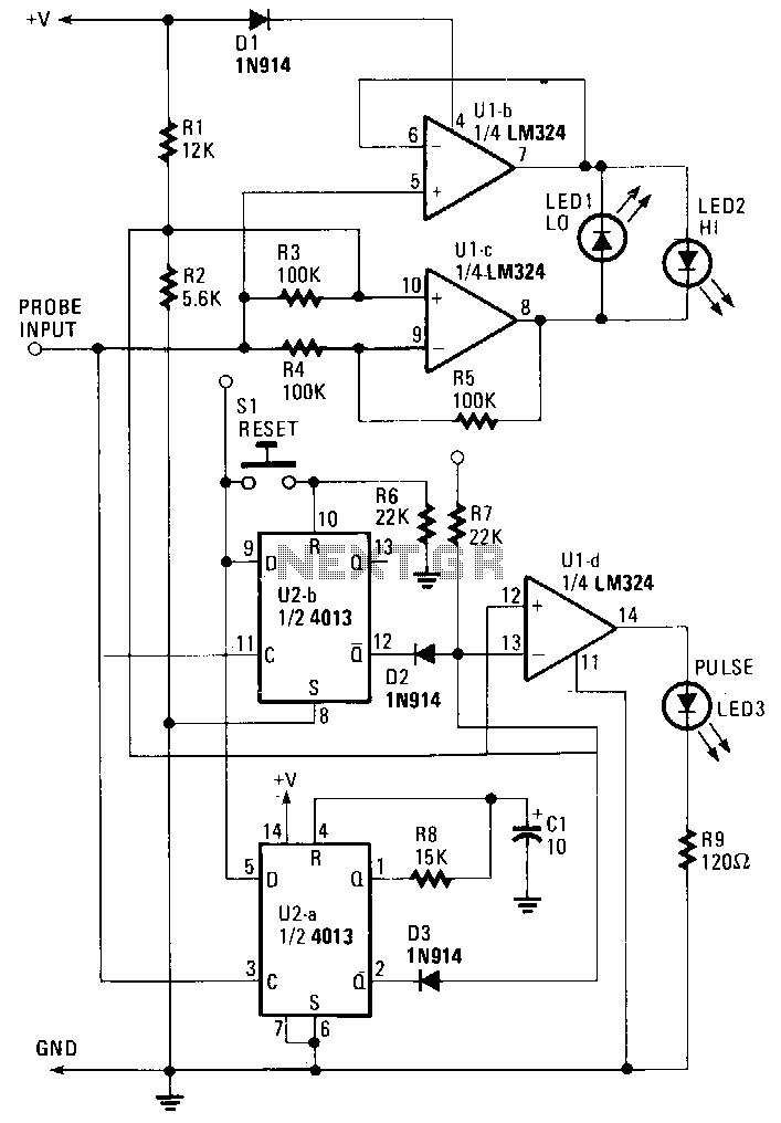
probe under Logic Circuits Circuit Diagram Input Test Circuit. This project will utilize an input