1GHz Simple Frequency Counter Circuit Diagram So what we are going to make is a frequency counter circuit, which can also be called as a frequency meter. To make this frequency meter 1) Simple LED Projects Using AVR Microcontroller. October 11, 2017. Keypad Door Lock using AVR Microcontroller - Atmega16. September 10, 2017. 5 Comments For the general theory of operation of this circuit and notes on frequency counting of this pic frequency counter click here. PIC frequency counter schematic using LCD and TMR0 and TMR1. (Click diagram to open a pdf.) PIC Frequency Counter: Hardware. The hardware is simple and the main blocks are shown in the diagram below.
Circuit Diagram: Using TIMER of 8051 for Measuring Frequency: 8051 microcontroller is a 8 bit microcontroller which has 128 bytes of on chip RAM, 4K bytes of on chip ROM, two timers, one serial port and four 8bit ports. 8052 microcontroller is an extension of microcontroller. To configure port 3.5 as counter, TMOD register values is set to 0x51.
![[SOLVED] - Digital Frequency meter -- Circuit desing Circuit Diagram](http://www.qsl.net/va3iul/Homebrew_RF_Circuit_Design_Ideas/0-99kHz_Frequency-Counter_G0UPL.gif)
Frequency Counter Circuit Working and Applications Circuit Diagram
To make calculations trivial using a 1 second gate time (T) gives a direct reading of frequency from the edge counter. Making a frequency counter for frequencies up to 65.536kHz is easy as the counters in a PIC chip can count up to 65535 without overflowing. Up to 65.535kHz all you do is wait for 1 second while the count accumulates, read the

Following is the code for Frequency Counter Circuit using 8051 Microcontroller. Frequency Counter Circuit Operation. Make the connections as per the circuit diagram and apply the Pulse generated by Arduino at Port 3 Pin P3.5, which is the Timer 1 Pin. As I have configured the Timer 1 as counter, using the TCON Bit TR1, I will be counting the
100MHz frequency counter with PIC16F628A Circuit Diagram
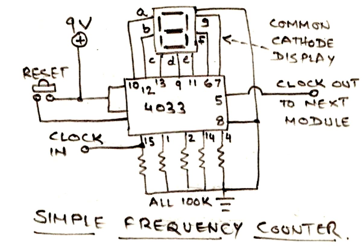
The first frequency counter circuit concept discussed above involved the IC 4026 for the intended frequency measurements over 7 segment common cathode displays. Now I have explained a couple of more circuits using IC 74LS47 and IC 4033 and see how these ICs can be configured into specific frequency counter designs, as I have explained below.