Overall circuit diagram of piezoelectric energy harvesting system with From Fig. 1, it can be seen that the energy acquisition converter consists of a piezoelectric, photoelectric transducer, interface circuit, power conversion module, acquisition module, and drive module. Composed of dynamic module and management control module. Optoelectronic, piezoelectric transducers, and interface circuits form the input terminal, which converts vibration energy and light

In today's research landscape focused on efficient energy utilization [2, 3], nanogenerators (NGs) and supercapacitors play pivotal roles in harvesting energy from microenergy sources [4, 5].However, the unpredictability of these sources challenges device reliability, prompting exploration into hybrid solutions that can harness energy from multiple sources simultaneously or intermittently.

Efficiency RF/Solar/ Triboelectric/Electromagnetic ... Circuit Diagram
Power management circuit design is another critical challenge for hybrid energy harvesting. Outputs in alternating current form are typical for piezoelectric and electromagnetic harvesters. Rectification, energy storage and voltage stabilization are necessary to accumulate collected charges on a single storage.
![[PDF] Hybrid energy harvesting technology: From materials, structural ... Circuit Diagram](https://d3i71xaburhd42.cloudfront.net/b7e3404e75d04e966dfe6c345b38ab972d5ac7f9/20-Figure16-1.png)
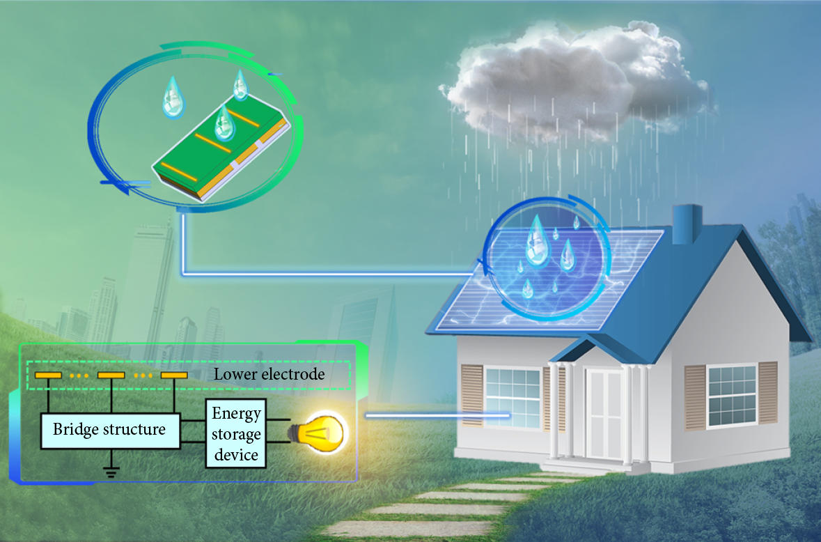
Hybrid energy harvesting systems are widely combined with various sensors to form intelligent systems due to their efficient energy harvesting and sensing performance. Feng et al. integrated a hybrid energy harvesting device, power management circuit, sensor, microcontroller, and wireless communication module to create an intelligent ocean buoy in wireless sensor networks). As traditional energy sources continue to deplete the cost of their utilization continues to increase. This fact has generated a growing interest in energy harvesting on a global level. Figure 1 illustrates how a simple energy harvesting scheme is employed to convert and store ambient energy into electrical energy.
Design and optimisation of magnetically Circuit Diagram
To further enhance the energy-harvesting performance of TENG, hybrid energy energy which was measured as an open-circuit voltage (dimension: 3 × 3 × 0.025 cm; dielectric constant: 3800 V/m

This paper presents a comprehensive exploration of a Hybrid Energy Harvesting System designed to harvest energy from diverse sources, including 2.4 GHz and 5.8 GHz RF energy, electromagnetic (EM) energy, solar energy, and triboelectric energy. The proposed converter operates within a wide input voltage range, maximizing efficiency and stability. A reconfigurable RF-DC converter is used for