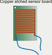
Programmable Humidity Controller Circuit Circuit Diagram The humidity sensor DHT22 is an affordable and easy to use sensor. To use this sensor with arduino boards you need to have DHT library file, you can get here. Circuit diagram . To wire up this sensor with arduino follow these steps, first connect bias to sensor that is +Vcc 5 volt to pin 1 and Ground GND to pin4. Then put external resistor 10K
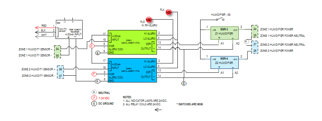
The simple programmable humidity sensor circuit I have explained in this article can be used for controlling or maintaining a suitable level of humidity inside a close premise. The circuit could be used in poultry farms or similar areas where humidity level becomes crucial for keeping the animals healthy. The idea was requested by Mr. Tanvir
Humidity Sensor + Arduino : 5 Steps (with Pictures) Circuit Diagram
Data: After sending the response pulse, DHT11 begins to transmit sensor data containing the values of humidity, temperature, and a checksum byte.The size of the data packet is 40 bits or 5 bytes. The first two bytes contain the values of relative humidity. The first byte contains the humidity integer data and the second byte contains the humidity decimal data.
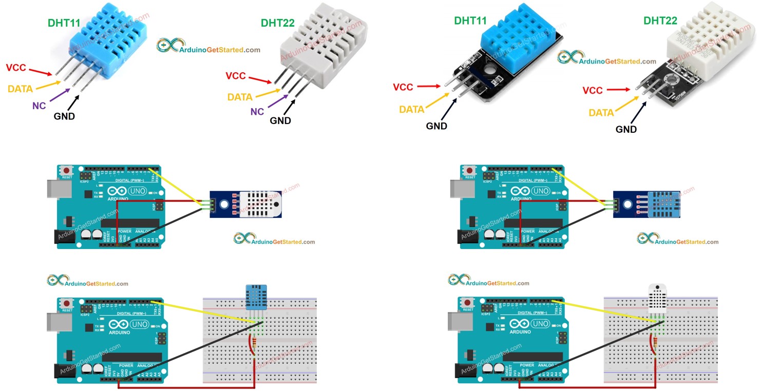
Learn how to use temperature and humidity sensor with Arduino, how to connect DHT11 or DHT22 temperature and humidity sensor to Arduino, how to program Arduino step by step. The detail instruction, code, wiring diagram, video tutorial, line-by-line code explanation are provided to help you quickly get started with Arduino. Find this and other Arduino tutorials on ArduinoGetStarted.com.
Humidity Sensor : 4 Steps (with Pictures) Circuit Diagram
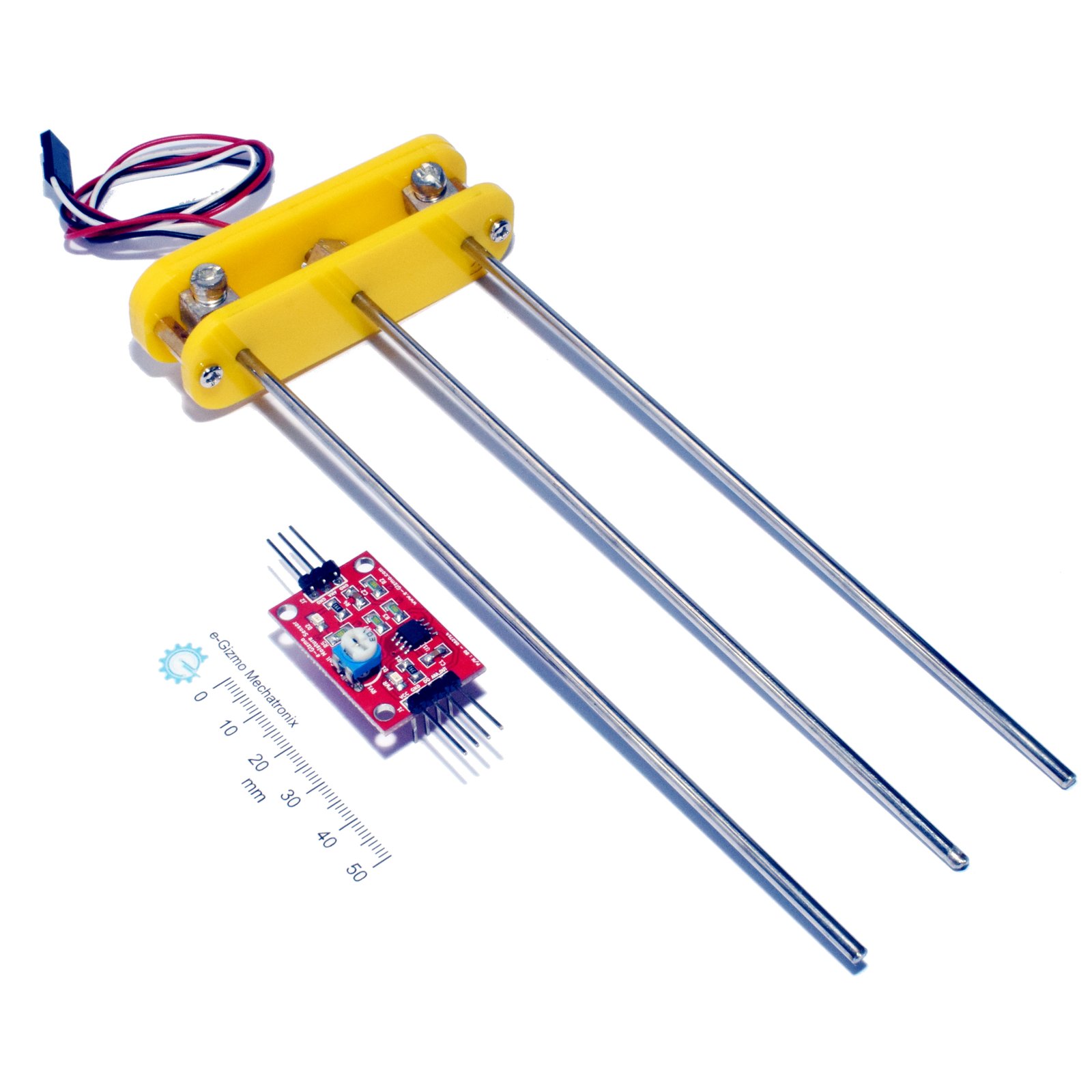
Working of Humidity sensor Circuit: In this circuit we are using an Integrated Humidity Sensor HIH-4030, three Op-Amps to sense the output from the sensor and switches the indicator LED's based on its intensity. For showing the results we have 3 LED's. The sensor is very simple and has 3 pins.
The DTH11 is a sensor designed to sense the moisture level present in any matter.hobbyist use to implement them into the prototype and make a prototype of it.Usually, the DTH11 consists of four pins out which three are used for the implementation. The pins are accordingly ordered as . VCC pin; Data-out pin; GND pin

Humidity Sensor with Arduino Circuit Diagram
In our previous article, I have explained how to interface temperature humidity sensor with arduino and read out displayed on serial monitor of arduino IDE. In this post I have explained how to display the reading on a 16x2 LCD display for the proposed digital temperature/humidity meter using Arduino.
